By Andy Finkbeiner
Photos by Ron Valera
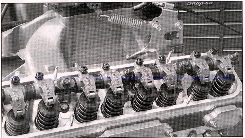
Mopar engine builders have one advantage over the bowtie boys when it comes time to build up that big block. Mopars come from the factory with beefy shaft-mounted rockers while the Chevy guys have to pay a ton extra for that feature.
You just don’t see rocker arm girdles on a Mopar big block since the stock shaft is plenty rigid just the way Ma made them. (Come to think of it. you don’t see many main bearing girdles on Mopar big block.. either, must be a whole Mopar anti-girdle thing going on here.) Of course, that nice rigid setup which the factory provided us does have one drawback, it isn’t very easily adjustable.
Forty-five years ago when the engineers at Chrysler chiseled the big block valvetrain drawings onto the stone tablets, they probably didn’t take into account guys running 0.650″ lift solid roller cams on the street. And even if they had looked that far
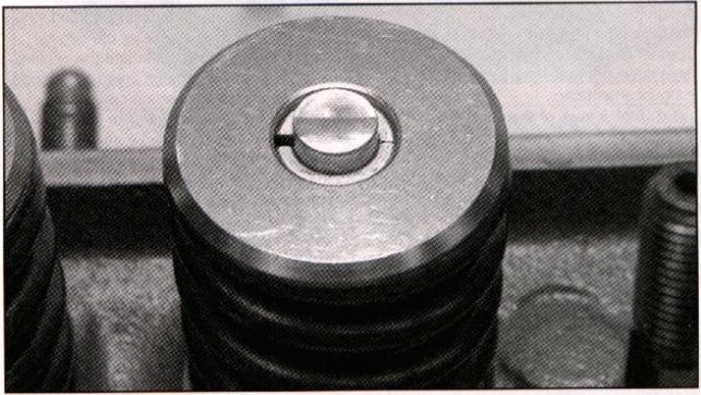
1. If you are planning to run a big stick then the first thing to do would be to assemble a mockup using all of the planned parts. Put machinist dye or something similar on the valve tips and then rotate the motor over a few times by hand. Pull the rocker assem-bly back off and examine the wear pattern on the valve tips. What you want to see is a nice narrow pattern that is centered on the valve tip. in tius picture we see a paiiern that is a little wider than desired and it also isn’t perfectly centered. Since the wear pattern is offset towards the rocker shaft we know that the rocker arms are a tad too short.
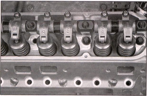
2. Starting in 1963. tic big block heads all came from the factory with rocker shaft supports machined into the cast iron head. By making this a one-piece design, the entire assembly is made very rigid. In this picture we see a rocker arm assembly from RAS bolted onto an Edelbrock head with integral rocker shaft supports. High quality aftermarket parts like this are made to factory specifications, which means that they will bolt together easily. However, if your application takes you outside of original design parameters, your parts might not align properly throughout the entire range of motion.
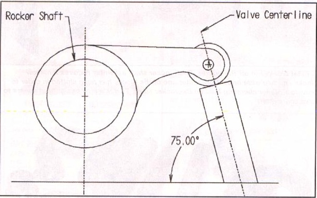
3. This CAD drawing shows the basic relationship between the rocker shaft, the rocker arm and the valve in a big block Mopar. Notice that the valve is inclined at a 15-degree angle from vertical. This 15 degree angle really causes a lot of trouble when we start to modify things. For example, valves that are longer than stock are not only taller, the tips are also closer to the center of the rocker shaft. And the correct length of the rocker arm depends on how high it is mounted. The lower you mount the rocker arm, the longer it needs to be to still reach the valve.
into the future, they still had to design a valvetrain that was economical to produce and would work just fine in your average pickup truck or motorhome. So they designed a system which was easy to manufacture and that works great for valve lifts of 0.400 to 0.5001 Not that there is anything wrong with this design, it just isn’t optimized for modern hi-pa cam lifts and spring pressures.
When we start to crank the valve lift close to double what the original design was
intended for, and then add in valve spring pressures that are four or five times greater than the original design, it isn’t too surpris-ing that we might need to make some changes to the basic geometry. Fortunately, there are some modifications that can be made to the Mopar big block valvetrain in order to optimize the geometry for longer life and more power. These modifications do require access to a machine shop and therefore are not for the faint of heart, but they might be just the ticket if you’re trying
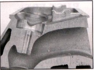
4. Dude, where’s my head? Cut away Stage VI head shows both the curved rocker arm support section and the relationship to the angled valve guide,.
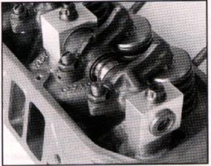
5. Here we see the rocker shaft support ed by a set of custom machined support blocks. The rocker shaft can be raised or lowered in relationship to the valve tip by machining the bottom surface of these support blocks. Or, if only small changes need to be made, flat shims can be installed under the support block.
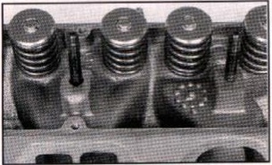
6. In preparation for the use of billet rocker shaft blocks, this 906 head has had the rocker shaft supports milled down to a flat surface. There is no reason to mill off a lot in this area, just cut it down until you eliminate the curved shaft support surface. This is an easy operation on a Bridgeport since the rocker surface is parallel to the deck surface. No fancy angle plates or setup is required.
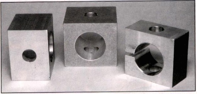
7. Billet blocks hot off the griddle. Each rocker shaft assembly requires 2 narrow blocks and two wide ones. Notice that one of the blocks has been slotted in order to provide a higher clamping load on the rocker shaft. This is a new design that seems to have some merit.
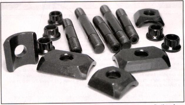
8. Use the good stuff if you have a monster bumps tick. Here we see a collection of ARP studs and nuts, and the heavy-duty rocker arm shaft hold-downs from HAS. These hold-downs would work with a rocker shaft that was in the stock position. Studs reduce the chance of stripping out the threads in the head when you tighten down the rocker shaft against the force of a bunch of burly valve springs.
to sort out the last bit of power from a combination. The first place to start is to check out your existing setup to see if you have a problem. If your cam has less than 0.550″ lift of cam you probably do not need to worry about valvetrain geometry so go ahead and skip to the next article where E-Booger examines Miss Mopar to see if she is numbers matching.
The goal with any valvetrain geometry optimization is to get the rocker arm centered over the valve tip as the valve travels through its entire range of lift. Not
| RATIO RATIONALE
|
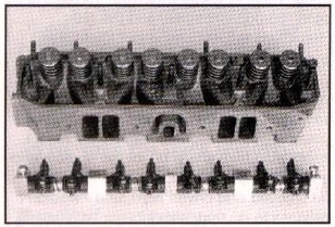
9. Here all of the support blocks and rocker arms are mounted onto the rocker shaft assembly. This particular assembly uses lsky rocker arms but the same idea works for other brands. However, rocker arms from different companies vary in width, which means that the support blocks need to be custom built for each application in order to properly line up the rocker arms over the valve tips. You can’t see them in this picture, but each rocker arm has a hardened shim on each side of it to control the oil flow and to protect the aluminum blocks from rubbing wear.
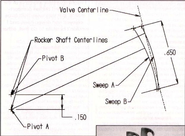
10. This CAD drawing shows us how to optimize the geometry of our valvet rain for a 0.650″ lift cam. The curve labeled sweep A is the travel taken by the rocker arm roller across the valve tip with the shaft in the stock location. Sweep B shows the same rocker arm travel after the shaft has been raised 0.150 inches. As you can see, the sweeping motion, or scrub, across the valve centerline has been reduced. Also, the rocker roller is now traveling back and forth across the center of the valve and not just to one side.
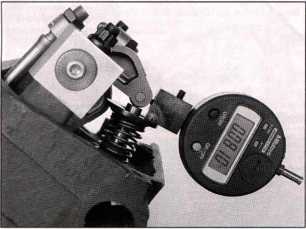
11. Here is a handy way to measure how much the rocker arm scrubs across the valve tip. The magic gnomes at AR Engineering built this too/ to verify the CAD data and to use in the field when we don’t have access to our CAD workstation. With the shaft mounted in the stock location, this rocker arm had a total sideways scrub of 0.081 inches over 0.650 inches of valve lift. Subsequent testing showed that raising the rocker shaft by a 150- reduced the total sideways motion to only 0.038 inches and centered the travel on the valve stern. Your mileage may vary.
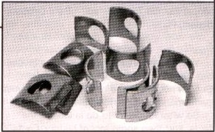
12. Tapered shims like these are an inexpensive way to raise the rocker shaft. While not as rigid as the billet block method, it is a lot quicker and easier. These shims were purchased from Bob Mazzolini Racing, or you can make ’em yourself with some scrap metal and tin snips.
only do you want the travel centered over the tip, but also you want to minimize the scrubbing motion made by the rocker. And don’t forget. you want the rocker to be centered over the tip in the side-to-side direction also. Lots of things to keep track of but don’t worry, we have pictures for you to follow.
CONTACT LIST:
Shims and Rocker Arms
Bob Mazzolini Racing,
3199 Columbia Avenue,
Riverside, CA 92501;
909-787-8783
Rocker Arm Assemblies and hold-downs
Rocker Arm Specialist (RAS),
19841 Hirsch Court,
Anderson, CA 96007;
530-378-1075;
www.shastacounty.com/rockerarm/
Rocker Arm Assemblies and related gear
Erson Cams,
550 Mallory Way,
Carson City, NV 89701;
775-882- 1622;
www.mrgasket.com/erson-main.html
AR Engineering
www.ARengineering.com
